ESP32 Matrix Shield (Mini 32)
The ESP32 Matrix shield is a kit for the Mini 32 ESP32 Development board for connecting into RGB LED panels. It's a much quicker and tidier way of connecting up these displays.
ADDITIONAL PARTS REQUIRED
As well as the ESP32 Matrix Shield, you will need the following items.
- RGB LED Matrix Panel* - $20 from Aliexpress
- Laptop Style 5V 8A power supply* - $10 from Aliexpress (might be possible to get cheaper than this one, 8A might be overkill too)
- Mini32 ESP32 Development Board* - ~ $7 on Aliexpress
'*' Affiliate Links
BOARD ASSEMBLY
NOTE: Please pay attention to the direction you are soldering the connectors!
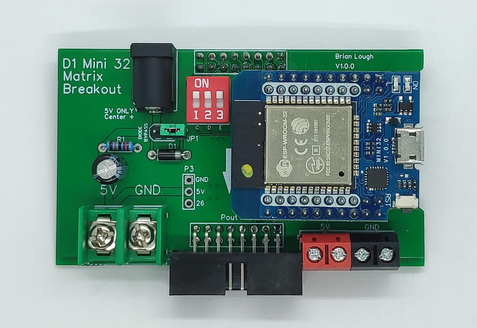
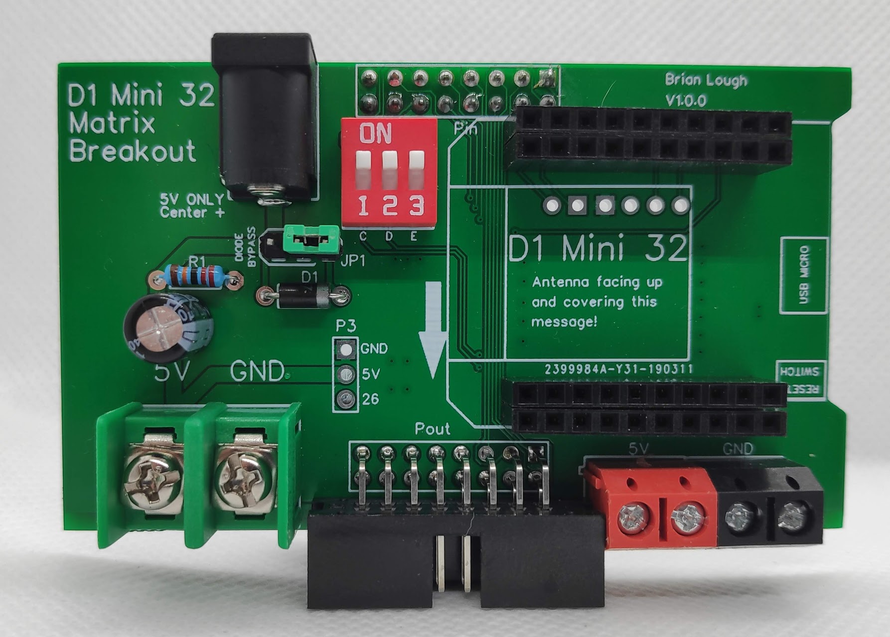
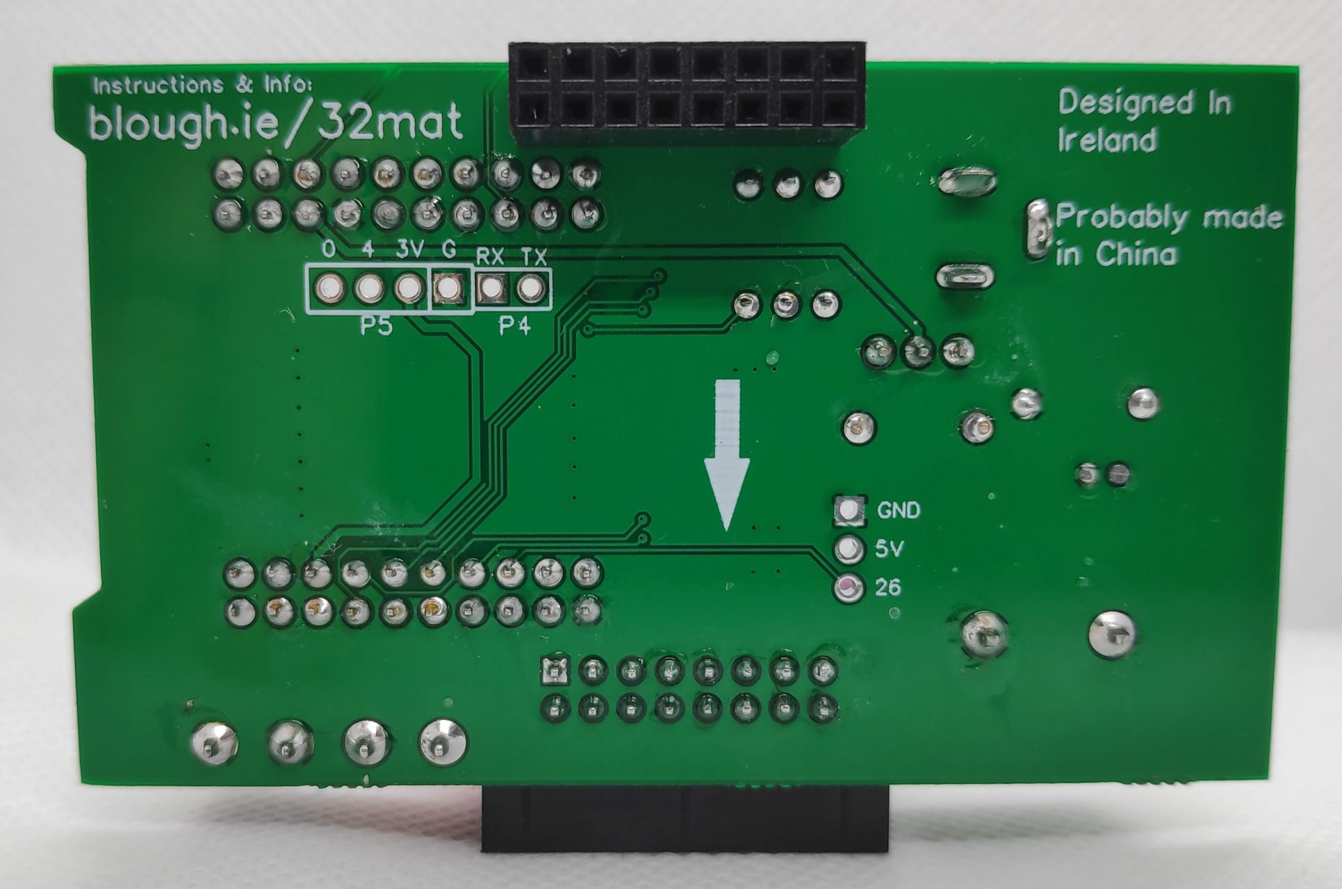
To assemble the boards, place the parts on the PCB as indicated by the markings on the PCB. All parts are places on the top of the PCB other than the connector marked "Pin" (As seen in the photos above). Pay attention to the polarity of the capacitor and the diode when assembling.
The green screw terminal and the P-out connector are quite close together, but they should fit in.
Place the jumper block on the right two pins of JP1 (Read below for more details on this)
CONNECTING THE SHIELD TO THE RGB LED MATRIX
To connect the shield, insert the "Pin" connector of the ESP32 Matrix shield into the "Input" connector of the panel (make sure the arrows on the shield match up with the ones on the display)
Insert the ribbon cable that came with the display into the "Pout" connector on the shield, insert the other end into the "Output" connector of the panel
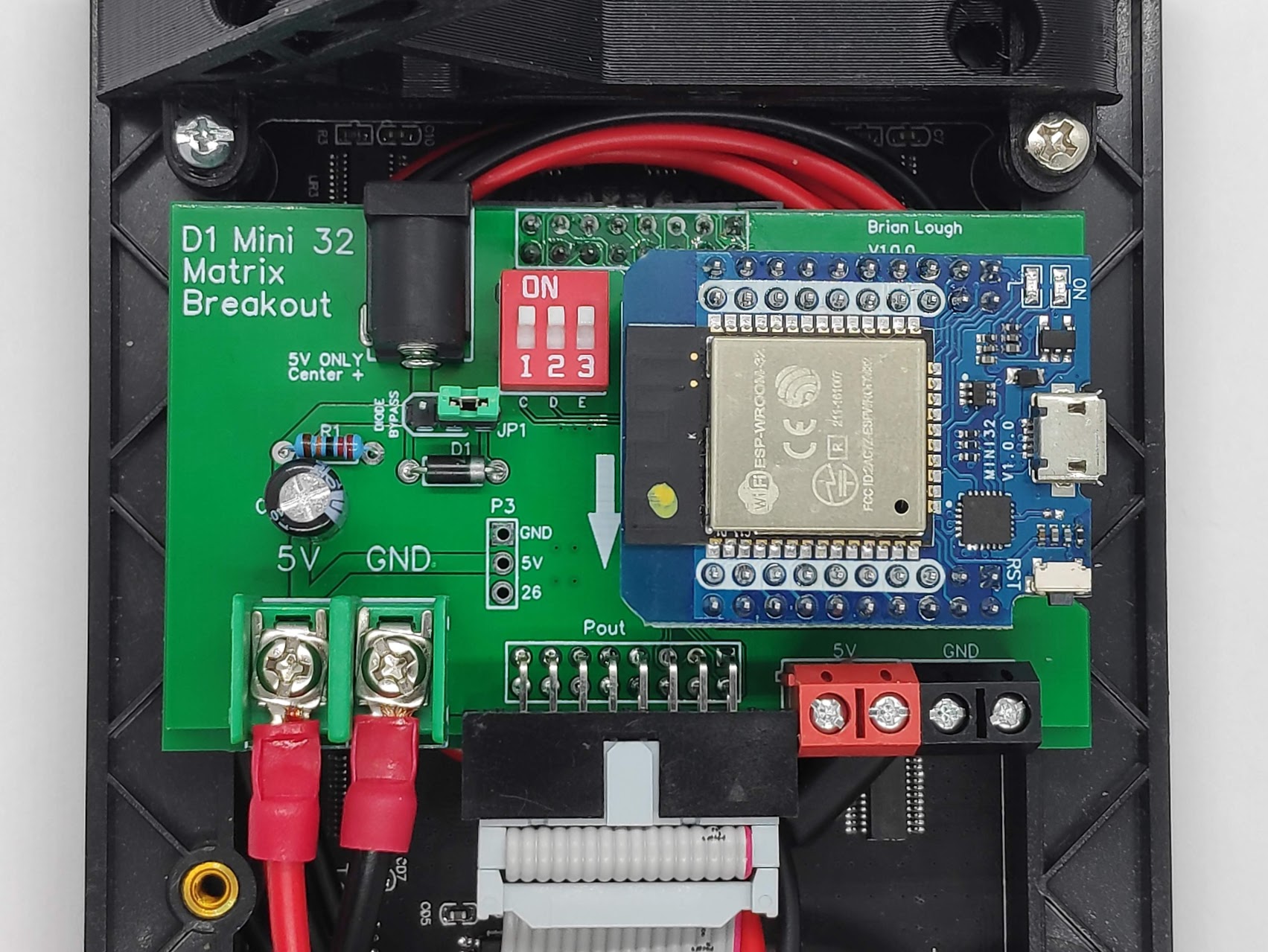
Plug the power wire that came with the display into the power pins of the panel. Attach the power wires to the Green screw terminals on the shield (Pay close attention to the polarity!)
There is a section on the Tindie listing about important measurements that is worth reading before buying to ensure the PCB will fit the display
CONFIGURING THE DIP SWITCHES
Some displays do not use all the pins that are connected to the ESP32. These optional pins are marked below as C, D and E. You can test if your display uses these pins by checking if they have continuity with ground.
If they have continuity to ground, you can switch the dip switch off.
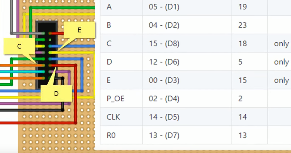
The pins you need to check on the ESP32 are 15 (E), 5 (D) and 18(C).
POWERING THE ESP32 MATRIX SHIELD
These displays require a 5V power supply capable of doing roughly 4A of current
My recommended way of powering this board is using the 2.1mm DC jack (center positive), but you can also use the optional screw terminals (Red and black in the above photo) instead if you choose.
The jumper block at "JP1" is controlling power going to the ESP32:
- Occupying the two pins on the right (as shown in the photo above), the ESP32 will receive 5V power from the panels power supply, but the ESP32 will not power the display as it is going through a diode. This is the one to use if you are not sure what to do!
- Occupying the two pins on the left (marked "Diode bypass"), will bypass the diode so the display will now receive power from the ESP32's 5v pin. In theory, if your are only illuminating a limited number of LEDs at a time you could power the display from the ESP32's Micro USB port, but I do not recommend this!
- Removing the block separates the ESP32's power supply from the matrix panel, I'm not sure the use case where you would want to do this but it is available if needed!
Using the display
To use the display you will need to install the following libraries
Adafruit GFX library from the Arduino library manager.
PXMatrix by 2Dom. Is the library for controlling the Matrix. It can be installed from the Arduino library manager.
Example sketch of using the board can be found here, it is the WiFi Tetris clock as seen below
The Tetris clocks are multiplying pic.twitter.com/wFd73TEDbT